This work expounds on electric energy quality issues using the Poynting Vector (PV). The cross-product E × H = P is the PV (where E and H are the electric and magnetic fields, respectively), and represents the density of power (W/m2) entering or exiting a certain surface at a given point. It is shown that components that do not contribute to a net energy transfer, are attributed to the nonactive components of the PV that are associated with three situations: 1. Phase displacement, 2. Current harmonics injection, 3. Load unbalance. The nonactive PV components can be viewed as carriers of polluting energy that negatively affects the energy transfer process and its conversion at the end-user. The developed analysis helps visualize the flow of electric energy in poly-phase systems and provides a theoretical base for the resolution of apparent power for three-phase systems with nonlinear and unbalanced loads.
Figure 1 shows an example found in many textbooks of the PV distribution for a coaxial cable with length d, connecting a voltage source us with a load. The current i flows through the inner conductor (radius a) and returns through the outer conductor (radii: internal b, external c). The cable impedance is assumed negligible; thus, the voltage along the cable is constant and equal to the source voltage us.
Figure 1. Coaxial cable: geometry and Poynting Vector distribution; Negligible voltage drop cable.
A sketch of the PV stream lines is shown in Figure 2a. It depicts the flow of energy through a cable segment at a certain time. The flow of active and nonactive energies is sketched in Figure 2b. Even in the case when the load is purely reactive (γ = 90°), the PV axial component at z < d will have an active component that carries energy ultimately impinged into the conductors by the radial component and converted into heat.
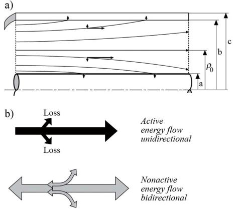
Figure 2. Coaxial cable: (a) Poynting Vector distribution. (b) Active and nonactive energy flow.
A question that frequently puzzles engineering students, stems from the fact that in a perfectly balanced three-phase system the instantaneous power is a perfectly constant quantity equal to the active power P=3UIcosψ, in spite of the existence of reactive power Q=3UIsinψ, where ψ is the phase angle between the line currents and line voltages. The source of confusion rises from the mutual cancellation of the oscillations characteristic to the flow of nonactive power. The answer to this question becomes evident when the PV is observed. In Figure 4 is sketched an equilateral system of three conductors and the corresponding E and H fields. The total PV was calculated for two extreme cases; first, for a unity power factor load, and second for a zero power factor load.
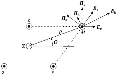
Figure 3. Three-phase, three-conductor system: Electric and magnetic fields and Poynting Vector
The three-dimensional graphs are given in Figure 4. When the load is noninductive, Figure 4a, the energy always flows toward the load. The total instantaneous power is constant, however the power density pattern is nonuniform. The flow of energy reminds one of the action of three cylinders that unidirectionally pump energy in a sequential order. In Figure 4b is shown the energy flow for a purely inductive load. Each conductor is surrounded by PVs, propagating back and forth. The value of total power transferred p, is always zero, save for the amount that covers 3RI2, that is through the external surfaces of the conductors by the tiny radial components of PV. The PV patterns repeat every half-cycle π/ω, and every sixth-cycle, π/3ω, the same pattern is shifted 120°.
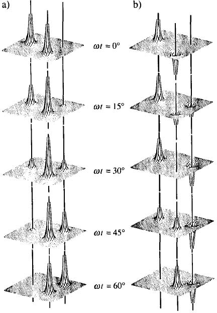
Figure 4. Poynting Vector envelopes for the ideal system sketched in Figure 3: (a) Unity power factor. (b) Zero power factor.
The PV distribution for an unbalanced system is obtained from the superposition of positive and negative sequence components. The interaction between the positive-sequence electric field E caused by the phase voltages and the magnetic field caused by the positive sequence currents yields patterns identical to the ones shown in Figure 4. The interaction between the positive sequence E and the negative sequence field H has a net transferred power zero, and is characterized by energy pumped from and to the load.